
Increases in design complexity of any digital circuit necessitates increased efforts spent on verification. This is resulting in verification of a design being shifted earlier and earlier in modern IC design. The problem of tackling the verification of a digial system is difficult. A subset of this effort would be spent verifying isolated functional blocks.
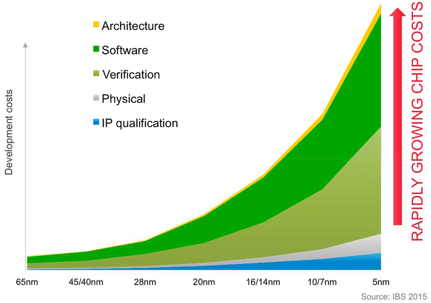
Figure 1. Increase of verification costs with decreasing feature size(Pre-Silicon Verification Using Multi-FPGA Platforms: A Review)
For hobbyist designers, the problem space is much smaller, but functional verification is still a useful tool which can help you in your design process.
As of Yosys 0.46, a new functional backend infrastructure was added to allow for the integration of your own verification process.
In this post I will demonstrate how to configure it to check for the verification of a simple 4bit unsigned adder using Rosette. Rosette is a solver-aided programming language built on top of Racket. Rosette is super useful to us as it plays the role of our SMT solver which can allow us to rigorously check for the functionality of our block given a specification.
// 4-bit unsigned Adder
module adder(
  input [3:0] a, b,
  output [3:0] c
);
assign c = a + b;

endmodule
Using the built in Yosys commands we can very simply convert our Verilog code into Rosette/Racket code. In the following Makefile snippet I’ve went ahead and appended an echo "(provide (all-defined-out))" >> verif/adder.rkt to the last line of the file. This tells Racket that we want to access each idenfitier within our generated Racket representation of our module.
# Generate funcitonal rosette for adder
adder.rkt: adder.v
	yosys \
		-p 'read_verilog -defer $^' \
		-p 'prep -flatten -top adder -nordff' \
		-p 'clk2fflogic' \
 		-p 'write_functional_rosette verif/adder.rkt'
	echo "(provide (all-defined-out))" >> adder.rkt
This now gives us an adder which takes in some input struct and some state struct and gives us an output struct. Given the simplicity of our adder, the state struct is completely empty. whilst the input struct takes in 2 4-bit vectors a and b.
#lang rosette/safe
(struct adder_Inputs (b a) #:transparent
  ; b (bitvector 4)
  ; a (bitvector 4)
)
(struct adder_Outputs (c) #:transparent
  ; c (bitvector 4)
)
(struct adder_State () #:transparent)
(define (adder inputs state)
  (let ((a (adder_Inputs-a inputs))) ; (bitvector 4)
  (let ((b (adder_Inputs-b inputs))) ; (bitvector 4)
  (let ((c (bvadd a b))) ; (bitvector 4)
  (cons
    (adder_Outputs
      c ; c
    )
    (adder_State))))))
(define adder_initial
  (adder_State))
(provide (all-defined-out))
Now we can start working on our top level verification module. In order to use Rosette and the Rosette/Racket representation of our adder, we would need to include them in our new top level file.
#lang rosette/safe
(require "adder.rkt")
From this point onwards we can start leveraging the power of Rosette. We want to create symbolic constants which will serve as placeholders for the input/state variables we are interested in verifying over. In our case this would be the 2 4-bit inputs to our adder. Rosette allows us to define types such as a 4-bit integer, which was used to specify x and y, the inputs to our adder model.
; definitions
(define int4? (bitvector 4))
(define-symbolic x int4?)
(define-symbolic y int4?)
From here on out we can start defining our satisfiability model. We want to define some check-sat function which takes in 2 input variables a and b which will represent our inputs. We want to pass this into the adder with out adder_State aswell. In this case, we can do this since our state is empty otherwise we would also add some symbolic state input to our satisfiability model.
Through the use of assertions and assumptions we can now start iterating over our design space. assumptions allow us to constrain the possible set of variables we are iterating over and assertions constrains the legal functional behaviour of our model. In our case, we know that in our 4-bit unsigned adder, we expect that our output is greater than any of our inputs. We can check this using the bvule comparison operater.
(define (check-sat a b)
  (define out (adder_Outputs-c (car (adder (adder_Inputs a b) adder_State ))))
  (assert (bvule a out))
  (assert (bvule b out))
)
Once our procedure has been denoted, we can then see if our model satisfies our specifications on all legal inputs.
(define cex (verify (check-sat x y)))
In our case we get an output telling us that adding 0xe to 0x6 gives us an incorrect answer (due to overflow), so our module combined with our specification is unsatisfied! So we should increase the width of our output if we do not wish to constrain inputs are not constrained and we do not expect this from our module.
(model
 [x (bv #xe 4)]
 [y (bv #x6 4)])
Now of course, this is a very simple example and will not work directly on sequential circuits. But the bring-up of open-source sequential verification support tools combining SAT checkers with perhaps angelic execution can end up being a very useful next step to empowering open-source verification.